Spray Balls (Self Rotating)
 The Spray Ball is a simple yet a highly effective device for the internal washing of process and storage tanks. A Spray Ball, powered by the cleaning fluid, generates a high pressure spray to clean every part of the vessel. There is only one moving part and no maintenance whatsoever . No lubrication is necessary which prevents any risk of oil or grease contamination of the product, making the spray ball ideally suited for hygiene sensitive applications.
These versatile units operate with a wide variety of chemicals and detergents frequently in hostile environments and temperatures upto 120 deg. C and water pressures around 2.8 Kg/cm2 Area of vessel coverage can be 1.5 meter to 3 meter.
Spray Balls are made of high grade stainless steel AISI 316. End connections are Tri-clamp or flanged. ”Spray Ball are offered in two designs viz. Multiple Nozzle design & Slit design .Complete mounting assemlies are available.
 View Pdf Catalogue


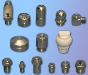 IEWI offer cleaning nozzles for a range of cleaning applications Whether you require a simple water rinse or cleaning with detergent, or a high impact wash or sanitising with oxidising to reduce microbial contaminants, we have a nozzle for you.The nozzles are available in various designs including solid cone nozzles, V-jet nozzles, flat-jet nozzles, high -impact nozzles & self-rotating nozzles.
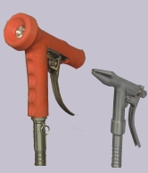 Heavy duty, stainless steel, Water Saver Nozzle is designed for cleaning applications in pharma, food, dairies, breweries, beverage & cosmetics. It does a better job with the least amount of water. The precision made nozzle enables the operator to get any type of stream of water to do jobs by simply pressing the lever. A slight spray is sent forth with slight pressure on the handle. The nozzle automatically shuts off the moment the lever is released, thereby eliminating water wastage. The nozzle is provided with molded rubber jacket to avoid thermal shock.
The unit operates on water max pressure of 10 kg/cm².
Inlet hose connections offered are ½" and ¾”.
The nozzle is available in two models for light duty and heavy duty applications.
 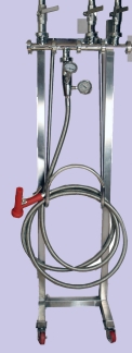 IEWI Hose Down Unit ( Mixing Battery ) provides instantaneous hot water economically by mixing steam and ambient water to the required temperature through a simple turn of a knob. The mixing battery is supplied with isolation valves, check valves, union joints, strainers and thermometer to know the temperature of the emerging hot water. Mixing battery provides industry with cheap hot water wherever steam is available, along with water. It incorporates a hydraulic fail safe device, so that when correctly installed and maintained, no steam regardless of its pressure can enter the mixing chamber until the water flows to raise the steam valve of its seat. When turned off at the outlet, there is an immediate and positive shut-off.When the outlet controls are opened and cold water flows into the mixing valve, the differential pressure across the piston causes it to raise, thereby compressing the fixed loaded spring and raising the steam valve of its seat. The steam thus released, is surrounded by the cold water in the defusing chamber, which on mixing provides instantaneous hot water at the outlet.When the outlet control is turned-off, there is then static water pressure which allows a larger internal stainless steel spring, to close the steam valve back onto its seat. This shuts off the steam completely so there is no steam present in the mixing chamber under any flow conditions .Mixing battery is available in various configurations viz. two services or three services or four services depending upon the customer requirement. Services can be potable water, steam, compressed air and dm water. Hose Down Stations are offered as mobile trolley mounted units or as wall-mounted units.
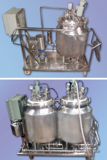 Clean-In-Place (CIP)/ Steam -In-Place (SIP) technology offers significant advantages to manufacturing facilities from efficient cleaning of process equipment & piping at lower costs to improved product quality CIP Systems are fully integrated incorporating tanks, pumps, valves , spray cleaning devices, ,heat exchangers, piping & controls without the need to disassemble all or part of the system, significantly reduces cleaning costs and minimises the handling of chemicals to provide a safer environment for plant personnel.
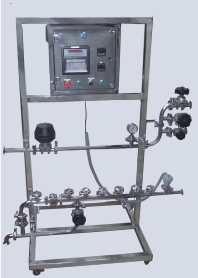 Pharmaceutical Sterilization-in-Place (SIP) systems are designed to sterilize a collection of process equipment after a batch of product is completed. Equipment such as bioreactors, fermentors and the accompanying tubing must be cleaned and/or sterilized before a new production cycle .
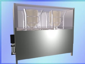 This machine is used for cleaning and sanitizing the external and internal surfaces of glass flasks. The flasks to be washed are manually loaded horizontally onto the machine frame. It is then tilted to a vertically inverted position The outer door is then closed to prevent water from spraying outside. A specially designed nozzle, which is mounted on a pneumatic cylinder is then inserted into the barrel. This pneumatic cylinder is operated with the help of a control panel provided on the machine. CIP liquid is then pumped into the flask for cleaning internal & external surfaces. Internal cleaning is done with the help of nozzles and the external cleaning is done with the V jet nozzles. The drain water is then drained through a drain port in the machine. As an optional feature a steam sterilization can be done for validating the flask after CIP is carried out. After the CIP cycles are over the nozzle is lowered the outer door is opened and the flask is then titled to a horizontal position and removed.
 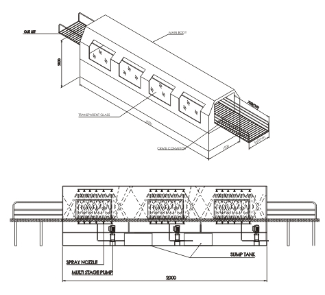 IEWI has designed crate washing station for dairy, ice cream, food, beverage & allied industries. The crates to be washed are conveyed by a chain conveyor into the wash chamber. The crates pass through high pressure water jet nozzles having accurate spray angles for washing. This ensures optimum cleaning in the shortest possible time. If desired the crates can be washed by detergent solution or hot water. Finally the residue liquid on the crates can be dried using hot air. The waste water is collected into a sump which can be recycled. A seperate electrical panel is provided for ease of operation
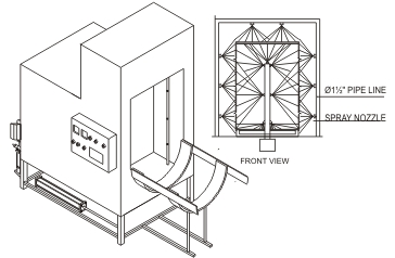 Industrial Equipwash Inc. manufacture barrel/drum washing units for cleaning of drums, barrels in bulk drugs,chemicals,pesticides etc The Drum Cleaning station consist of:A washing frame which support the cleaning compartment made of SS 316 grade. A cleaning lance, self rotating, covering 360° rotating action, self driven, powered by a multistage pump for internal cleaning.Array of cleaning nozzles for external cleaning with knife edge spray nozzles designed to wash external surfaces and custom made to reach even the most remote corner.
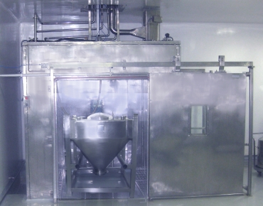 IEWI have developed various versions of the IBC Wash Stations keeping theapplication of the client mind as also the constraints that are normally existingat the site in the wash area.The IBC is first loaded on a specially designed trolley/ monorail . The door ofthe IBC wash station which is in the non-sterile area, is then opened andthe IBC is guided into the wash roomafter which is the door closes. The trolley mounted IBC is then latchedonto a conveyor mechanism, which is anin-built feature of the IBC wash station.The conveyor guides IBC and locks it atthe “point of washing”in the washing machine, the bank of sensors send thetrigger to the PLC which starts washingcycle. A specially designed self-rotary cleaning nozzle is introduced into the IBC.The pressure generated by the special purpose high pressure multistage pumpuses the nozzle to spin on its verticalaxis with a velocity sufficient to ensurea thorough cleaning of the internals of the IBC. External cleaning of the IBC is done with help of strategically positioned flat V-jet nozzles The time duration and the sequence of operation of the washing cycle is monitoredby a PLC each wash programmed beforea start of the process by the user. After the washing cycles are over steam sterisation can be done.
 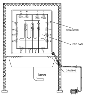 IEWI offer FBD Bag wash station keeping the application of the client in mind as also the constraints that are normally existing at the site in the wash area. The wash cycles follow the recipe set in the PLC normally would consist of wash cycles which can be decided by the user depending either on the size of the fbd bag and the SOP of the wash cycle to be followed. Typical wash cycle includes potable water rinse, hot water rinse, detergent wash,hot air drying etc. The recipe management of the PLC allows the user the flexibility of even selecting the sequence of wash cycles and time required to complete each wash.
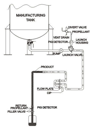 Removal and recovery of valuable product, from process pipe lines as well as expediting cleaning is an extremely important process. The most effective way to accomplish these tasks is with Industrial Equipwash Inc. Product Recovery System. When viscous products (creams, pastes, ointments) are pumped through tubing in a process system, a certain amount of product will be left behind. Residual will either dilute or leave large deposits attached to the inside wall of the tubing. While water and air are often used to remove this residual, these methods only work to a certain degree. The IEWI Product Recovery System works on a simple, yet extremely effective, principle. Our product recovery system consists of a launcher, a catcher and a pig (one-piece, solid molded urethane projectile). Prior to start-up, the pig is placed in the launcher located in the pipeline and just down stream from the pump. Once the run is completed, air pressure is applied to the pig to push it through the main pipeline, forcing the remaining product to a recovery point at the end of the pipeline. The projectile travels through standard 90° elbows until it reaches the catcher, and then the propulsion
